Component Animation
Making Components Move
Animation can be a useful tool to help visualize what is happening at any given time. Animations make it easy to tell if a machine is running, or a conveyor is moving with a quick glance at the screen, and it can help highlight which components aren't currently in use. There are two main ways of creating animation: actually moving all or part of a component, or cycling through a few different static images of a component that give the illusion of moving. Each method has its advantages. For example, making a dump truck move forward and backwards may be better accomplished with actually moving the component. It would be fairly simple to make the whole component move forward on its x coordinate, and then back the same amount. But, if the truck was instead stationary, and just its bed were moving up and down to simulate the truck dumping its cargo, it may be difficult to seamlessly move the component, since it would not just be moving on one axis, but would require careful rotation and movement combined. In this instance, it would be far easier to create a few static images of the truck with its bed in various states, and then cycle through those images fairly quickly so it looks like it is moving. Let's go over both methods below.
Components that Actually Move
To actually move components around during runtime usually involves binding all or part of an image or svg to the value property of a timer or signal generator. The symbol factory components all contain an Angle property. Binding the Angle property of a spinning part of a motor can help us visualize when the motor is running or not.
-
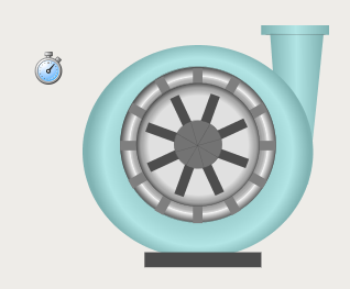
Pick out a component that you would like to animate. I used the Single Stage Compressor from the Symbol Factory. You will also want to grab a Timer Component.
-
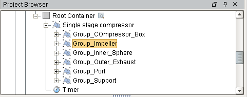
Expand out the Single Stage Compressor component. You will notice that the whole component is made up of many smaller pieces. We want to select the piece called Group_Impeller.
-
Bind the Group_Impeller's Angle property to the Value property of the Timer.
-
We now need to modify the properties of the timer to ensure a good rotation. Set the Delay (ms) to 200, the Step By to 10, and the Bound to 360.
-
You should now be able to set the Timer's Running? property to True, and your component will now animate. You can adjust the Delay (ms) to be lower or higher to adjust the speed at which the component rotates.
Giving the Illusion of Moving
With this method, you can make components look like they are moving without actually moving anything. What we do here is duplicate the component multiple times and modify each component to be a little different than the others, and then show and hide them in the correct order to make it seem like they move.
The following example uses a Signal Generator component to drive the animation, but any incrementing value can be used, such as the Value property on a Timer component, an accumulating value in a PLC, or the current time in seconds.
-
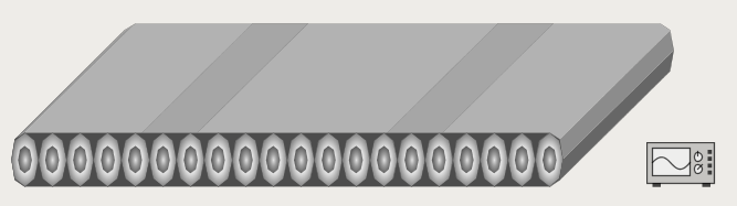
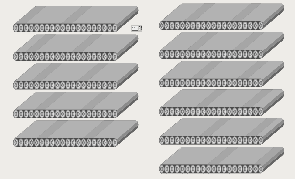
Pick out a component to animate. For this example, I selected the Horizontal Conveyor with Perspective from the Symbol Factory. I also dragged a signal generator on the screen.
-
Duplicated this component 10 times for a total of 11 conveyors.
-
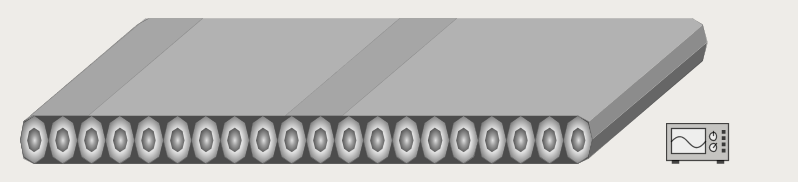
Select the first instance, expanded the Group_Conveyor_Belt, and moved the Path 4 and Path 5 Components. On this instance, I moved them both an equal distance left so that the leftmost component is on the left edge of the conveyor.
-
Repeat this with the rest of the components, except move them slightly to the right of the previous instance. Notice how the gray bars slowly move from left to right over all the components when viewed in sequence.
-
Next, stack them all on top of each other exactly. This is easily done by selecting all of the conveyors, then going into the Alignment menu and selecting both Align Centers Horizontal and Align Centers Vertical.
-
Once stacked, select the first Conveyor from the Project Browser (the one that has the bars on the far left), and place an expression binding on its Visible property that looks like this.
if({Root Container.Signal Generator.value} =0,1,0)Duplicated this across all of the conveyors, but increment the first number by 1 each time. The last conveyor (the one that has the bars on the far right) should have the following expression:
if({Root Container.Signal Generator.value} =10,1,0) -
Select the Signal Generator component. Set the Signal Type to Ramp, the Period to 1000, the Values/Period to 11, the Upper Bound to 11, and the Lower Bound to 0.
-
Setting the Running? property of the Signal Generator to True will now cycle through showing all of the conveyors, which will make it look like it is moving.
Animation in Scripting
Additionally, the system.gui.transform function can move and resize components from a Python script. More details can be found in the Scripting Appendix.
Similar Topics ...