High Performance HMI Techniques
About High Performance HMI Techniques
High performance HMI techniques and practices call for designs and displays which help the viewer make the best decision in the shortest amount of time after interacting with the HMI.
High performance HMIs often look basic and simplistic. They typically use gray-scale colors rather than the traditional graphics and bright colors for their displays. Conceptually, the High Performance HMI operates under the idea of visually contrasting critical and non-critical states. The power of this design philosophy is when something does go wrong, a high performance HMI will quickly guide the user to the source of the problem.
Traditional HMI

Traditional HMI Design
High Performance HMI
High Performance HMI Design
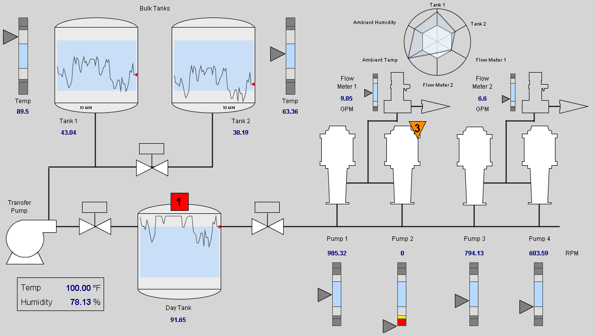
In Ignition, you create the high performance HMIs by using components such as moving analog indicators, sparkline charts, and radar charts. Here is a comparison of a traditional HMI next to a high performance HMI.
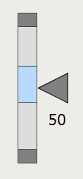
Moving Analog Indicator
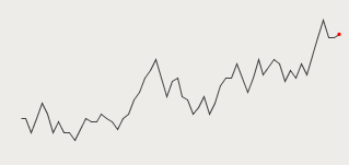
Sparkline Chart
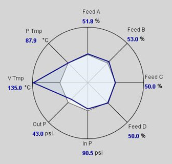
Radar Chart
Use of Color
Colors are an important consideration when designing a high performance HMI. Gray-scale colors are used instead of the traditional bright red, green, and blue colors.
The person that designs the HMI must understand the diverse audience that may view the HMI. For example, an operator may look at a motor on a traditional HMI. If it the HMI has colored the motor green, the operator may conclude that the motor is running. However, if a maintenance technician looks at the same motor, he may conclude that the motor is not faulted. These are logical conclusions. They reflect the respective interest of the person viewing the HMI where the operator wants the motor to run and the maintenance technician wants it to be working.
In reality, the motor is simply "scheduled" to run, meaning when it runs depends on its control mechanism. For example, the motor may run when there is product on the line or boxes on the conveyor. In other words, the motor may be periodically starting and stopping automatically.
A high performance HMI can eliminate this confusion by introducing a color that signifies a state of "scheduled." A common high performance HMI practice is to use a dark gray to signify a "scheduled" state for equipment. This color should never compete with more alerting colors that "pop" from the HMI resulting in the viewer's eye's being drawn to the portion of the HMI where the problem may be occurring.
Colors and Alarm Indicators
Color can play an important role in how an operator responds when problems do occur. High performance HMI design refrains from coloring equipment when the equipment is in a state of fault. For example, some equipment may still run when faulted. Instead, an optimized solution is to place an alarm indicator near the equipment in such a way that when the equipment is undergoing some fault, the alarm indicator renders with the appropriate color and shape. The object and the consequential color should signify the most important alarm state occurring for the equipment at that current time.
Technical Considerations with Colors
Some HMIs in industrial settings may temporarily lose their ability to render color because of various environmental factors. High performance HMI design incorporates this possibility by encouraging the use of descriptive text with color. For example, motors of two different colors may look the same on a color deficient HMI resulting in confusion for the viewer. Even worse, the viewer may misinterpret the motor state and assume everything is fine. However, if each motor has a descriptive text such as "Motor 1 is Faulted" and "Motor 2 is Running", the problem associated with a faulty HMI failing to display color is largely reduced by the HMI's high performance design.
Accommodating Color Blind Viewers
Common color combinations such as red and green and blue and purple cannot adequately be distinguished by those with color blindness. High performance HMI design accommodates color blind uses by combining colors with descriptive text as well as incorporating alarm indicators in unique shapes.
Alarm Indicator
The high performance HMI design techniques make use of an object called the Alarm Indicator which displays a colored shape when there is a problem. This works well with the high performance HMIs as color is only used when there is a problem. The Alarm Indicator can contain descriptive text in addition to the shape and color, and is usually placed near the component that is causing the problem. You can import the Alarm Indicator, shown in the example below, from these Cloud Templates.
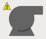
The Alarm Indicator represents different levels of alarm with different shapes, color, and descriptive text. For example, a motor that exists in an industrial setting is monitored by a high performance HMI. There are two alarms on the motor. The first is a high priority alarm associated with the motor when over heating, will display as a red square with the number 1. The second is a critical alarm associated with the motor becoming seized, will display as a yellow triangle with the letter 2. An Alarm Indicator is placed near the motor, positioned in such a way to clearly show motor that the indicator is referring to.
Given this scenario, a high performance HMI will show the Alarm Indicator as in the following examples:
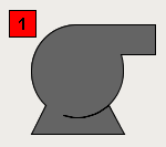
Example 1
The motor is critically faulted. This is the highest priority.
Example 2
Motor is overheating resulting in a high alarm.
Reducing Ambiguity
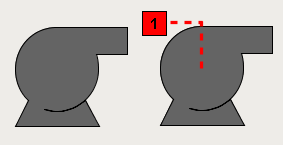
A high performance HMI design technique to reduce ambiguity incorporates a line from the Alarm Indicator to the object experiencing the alarm.
The following example shows how a simple dotted line can ensure that the viewer associates the correct Alarm Indicator with the correct motor.