ControlNet Example
Before we show you how to connect to a PLC5 through a ControlLogix Gateway using ControlNet, you need to understand what a connection path is and how to build one.
Connection Paths
Connections to ControlLogix, CompactLogix, PLC-5, MicroLogix and SLC Allen-Bradley processors through a ControlLogix Gateway require a connection path. The connection path is unique to your setup and is dependent on what modules the connection is being routed through.
Follow the Path
A connection path is exactly what the name implies. It is a path that when followed leads to a processor residing in a numbered slot of a chassis somewhere on site. You only have to follow the path and build the connection path as you go.
The first connection point between Ignition and the device is a ControlLogix Ethernet module such as an ENET, ENBT, or EN2T module. The slot number of this module doesn't matter and you don't need to specify it in the connection path.
Building the Connection Paths Entries
You need to have 6 numbers/entries to specify the connection path. The way you find each number is described in the following table:
|
1st Number |
Is 1 and means move to the back plane |
|
2nd Number |
Is the slot number of the module you want to move to |
|
3rd Number |
Is the exit port or channel of that module that you want to exit through |
|
4th Number |
Is the address of entry point to the next module (DH+ Station Number / ControlNet Address / IP Address of ethernet module) |
|
5th Number |
Is 1 and means move to the back plane (from this 5th Number, it starts repeating as the 1st Number) |
|
6th Number |
Is the processor slot number OR the slot number of the module you want to exit through |
The process of coming up with these numbers may sound complicated at first but after some practice it gets easier.
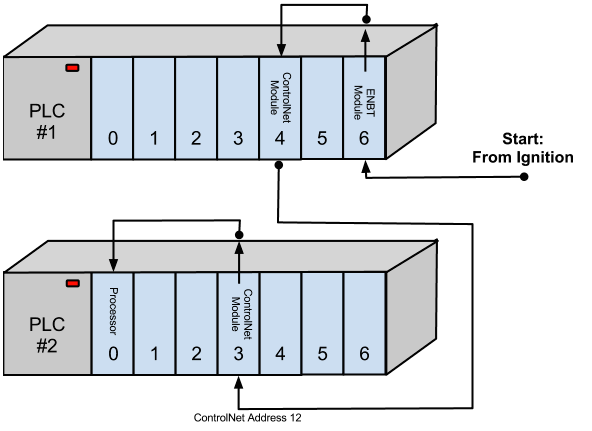
Here is an example, as pictured below, that has a connection path of 1,4,2,12,1,0 going from PLC 1 to PLC 2. The following table shows the walk-through for these numbers:
|
1 |
Move out of ENBT Module to the backplane |
|
4 |
Move to ControlNet Module in Slot 4 |
|
2 |
Move out ControlNet Port |
|
12 |
Move in ControlNet Module at ControlNet Address 12 |
|
1 |
Move out of ControlNet to the backplane |
|
0 |
Move to the Processor in Slot 0 |
Connecting to a PLC5 using ControlNet
To connect to a PLC5 through a ControlLogix Gateway using ControlNet in Ignition, do the following steps:
-
Go to the Configure section of the Gateway webpage.
-
Scroll down and select OPC-UA > Devices.
-
On the Devices page, find the orange arrow and click on Create new Device.
-
On the Add Device Step 1: Choose Type page, select Allen-Bradley PLC5, and click Next.
-
On the New Device page, leave all the default values and type in the following fields:
Name: PLC5
Hostname: type the IP address for the PLC, for example 10.20.4.62
Connection Path: 1,3,2,14 (1 means going to ControlLogix and going to the backplane in PLC 1, 3 is the slot number of the ControlNet module to move to in this example, 2 is the exit port of the ControlNet module, 14 is the address of entry point to the ControlNet module in PLC 2)
-
Click Create New Device.
The Devices page is displayed showing the PLC5 device is added to Ignition. The Status will show as Disconnected and then Connected.
-
To see all the tags, go to OPC Connections > Quick Client in the Configure section, on the OPC Quick Client page expand the PLC5 folder which contains all the folders with the individual tags.
Connection Path Entries for Different Module Types
How you specify your exit point from a module is slightly different depending on which module type you are using. You can only move in two directions once you are in a module, either out to the back plane, or out through the module port/channel.
Ethernet modules have ethernet ports and an IP address. ControlNet modules have ControlNet Ports and ControlNet addresses. DHRIO modules have channels and station numbers.
Below is a list of different kinds of modules and what numbers you specify in the connection path when you are exiting or entering those modules. When in a module, an entry of 1 will always take you to the back plane.
ENET, ENBT, and EN2T
Exiting
1 = Backplane
2 = Ethernet Port
Entering
IP Address
CNB
Exiting
1 = Backplane
2 = ControlNet Port
Entering
ControlNet Address
DHRIO
Exiting
1 = Backplane
2 = DH+ Channel A
3 = DH+ Channel B
Entering
DH+ Station Number (an octal value between 0-77)
You use these numbers to specify how to move out of the module, then you specify where you are moving to by either specifying the DH+ station number, ControlNet address, or the IP address of another ethernet module. Your connection path is always an even number of entries because there are two steps: out of a module and then in to another module. So if your connection path ends up with an odd number of entries, you have missed a step somewhere and have to go back and trace the path again.