Modbus Address Mapping
Because it can be very tedious manual entering OPC Tag information one-by-one, the driver offers an address mapping feature. This feature allows entering blocks of common addresses and the driver will create the individual addresses and display them in the OPC browser.
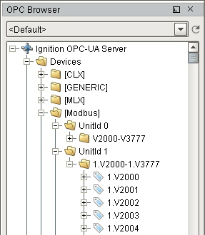
Another benefit of address mapping is that the addresses inside a device can have a different numbering scheme than the Modbus address. The Direct Automation DL240 is a perfect example of this. Address V2000, capable of holding a 16 bit integer, is Modbus Holding Register 1024. In addition, the DL240 addressing is in octal meaning there are no 8 or 9s. The sequence of addresses are: V2000, V2001, V2002, V2003, V2004, V2005, V2006, V2007, V2010, V2011.... V3777. This is not very straight forward.
Address Mapping Properties
|
Name |
Description |
|
Prefix |
A prefix applied to each mapped address as they appear in the OPC browser. Must compose of letters, numbers, and underscore characters. The following values are reserved, and may not be used: HR, IR, C, or DI |
|
Start and End |
Numerical values will be assigned to each mapped addresses. These properties determine the range of the numerical assignments. Follows the Prefix. The difference between these two values determines how many mapped addresses will be created. |
|
Step |
When enabled, adjacent addresses will be combined. This is commonly used to combine two words (16-bit addresses) into a double word (32-bit addresses). Please see the Floating Point or 32-bit Address Mapping for more details. |
|
Radix |
The base number of unique digits for modbus addresses. Determines what format addresses in the device are incremented and labeled (HR0, HR1,...HR9, HR10, HR11). Common values are 10 (decimal system) or 16 (hexadecimal). |
|
Unit ID |
The Unit Id for the device to use. When several Modbus devices are connected to a single IP address, the step determines which device the mapping should be applied against. A value of 0 means the first device, and should be used when only a single Modbus device is connected. See Address Mapping Multiple Devices for more details. |
|
Modbus Type |
The table each mapped address should run against, as well as the type and size of each address. |
|
Modbus Address |
The address in the device that mapping will begin at. Note that since the table has already been selected by the Modbus Type property, this number should range between 1-9999. |
Simple Mapping Demonstration
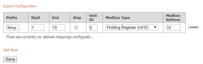
Temperature readings are being stored in 10 16-bit addresses: 40,010 - 40,019. There is a single Modbus device at the IP address (unit ID 0), and the addresses are decimal. The mapped addresses should appear in the OPC Browser as "Temp1", "Temp2", and so-on. The following configuration would be used:
Prefix: Temp
Start: 1
End: 10
Step: False
Unit ID: 0
Modbus Type: Holding Register (Int16)
Modbus Address: 10
Note that 40,010 (HR10) uses Modbus Address 10 as a starting point and not 40,010. The leading 4 is automatically entered for you when you select Holding Register from the dropdown. The same is true for all other types of tags: Inputs are 30,000, Discrete are 10,000, etc.
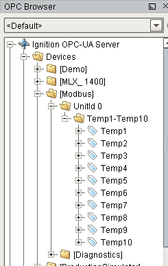
The above configuration would result in the following items appearing in the OPC Browser:
To specify the address mapping
-
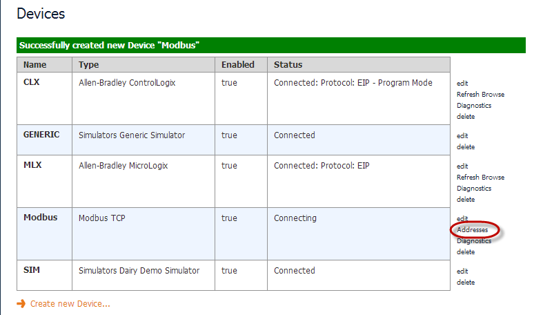
Click on Addresses to the right of your Modbus device.
-
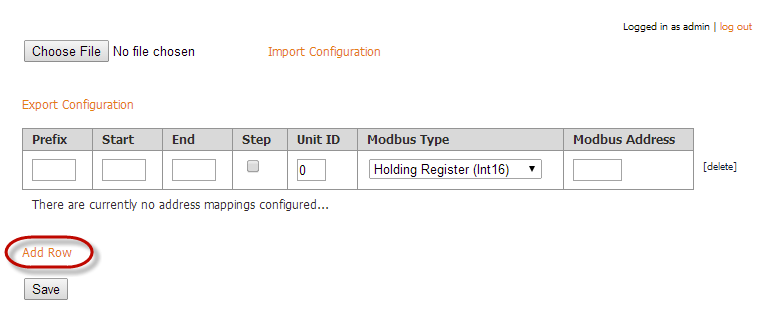
Click on Add Row.
-
Enter the mapping as follows:
Prefix: V
Start: 2000
End: 3777
Modbus Type: Holding Resister (int16)
Modbus Address: 1024
Radix: 8 (8 causes the addresses to be in octal, also known as base 8)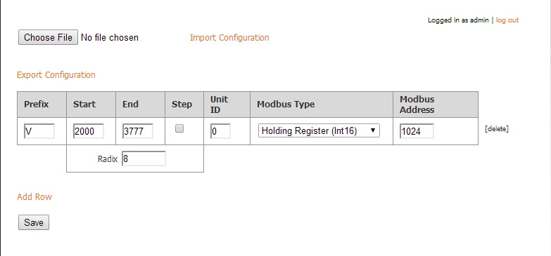
These settings map the Modbus address range V2000 to V3777 in octal to Modbus Holding Register addresses 1024 to 2047.
Note: The mappings for string data types cannot be entered. Strings can only be read or written using Modbus Specific Addressing. -
Click Save.
-
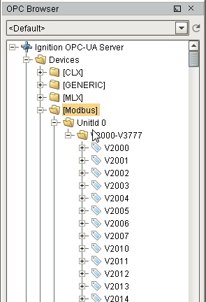
Go to the OPC Browser in Designer or the OPC Connections > Quick Client (on Gateway), open the Modbus folder.
You can now see all the Modbus addresses from V2000 to V3777 in octal.
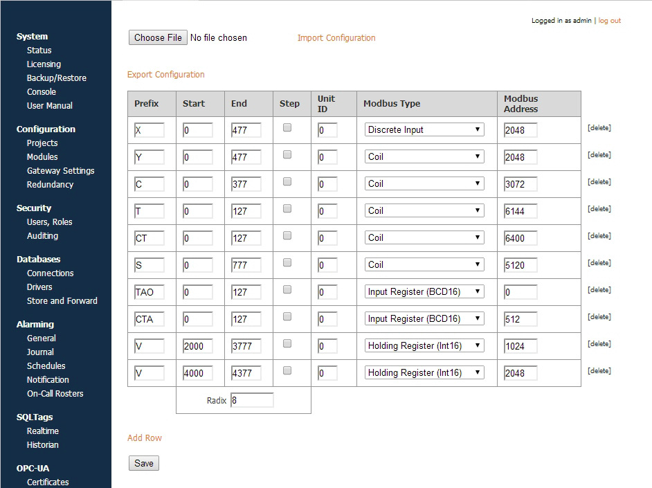
Here is an example of mapping for all of the Modbus DL240 addressing.
Address Mapping Multiple Devices
It is not recommended to communicate to multiple Modbus devices through a Modbus Gateway where Gateway has the same address. Therefore, do not add multiple Modbus devices with the same IP address.
Only add one Modbus device to the Ignition OPC-UA Server device list for Gateway and specify the different unit IDs in the address mapping. The unit ID is specified for each entry in the address mapping for the Modbus device. Notice in the example below, the Prefix, Start, End, Modbus Type and Modbus Address can be the same for two entries provided that the Unit IDs are different.
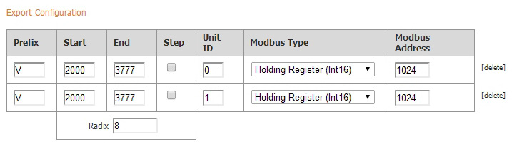
Now when browsing the Modbus device, the unit ID will show as a folder and the OPC tag path includes the unit ID as shown below. This only happens when more than one unit ID is specified in the address mapping otherwise the unit ID is eliminated.
Floating Point or 32-bit Address Mapping
Modbus only supports reading and writing to memory types of bits and 16-bit words. This is not very useful when reading from or writing to float point or 32-bit integers.
To workaround this problem, the Modbus driver is designed to read 2 consecutive 16-bit words and encode it into the desired data type.
To map float point addresses
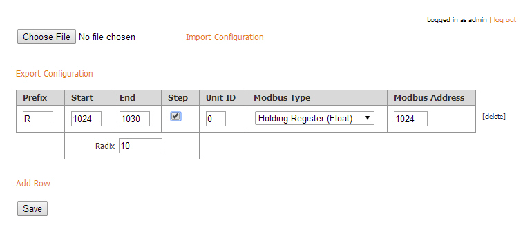
The Modbus address mapping below shows how to map float point addresses starting at 1024 and ending at 1030. With the box in the Step column checked, the addresses on the Ignition side will index by 2. In this case, R1024, R1026, R1028 and R1030 will be created.
Because Modbus Type of Holding Register (Float) is selected, the driver will read two consecutive 16-bit words and convert it to a floating point value. It also indexs the Modbus Address by 2 for each entry. In this case, R1024 reads from Modbus addresses 1024 and 1025 and converts them into a floating point value. When writing, the reverse of converting a floating point value into two 16-bits words is done before sending them to the device.
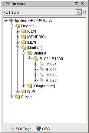
The following window shows what is displayed in the OPC Browser. Notice that the numbering is indexed by two and that it matches the Modbus address. With some devices, this allows the addresses displaying in the OPC Browser to match the addresses in the device.
Import / Export Address Mapping
The mapping configuration can be exported to a comma separated values (CSV) file. The CSV file can later be imported in other Ignition installations or similar devices.
You can find a few examples of CSV files on our website. To see the examples, go to:
http://inductiveautomation.com/downloads/extras
Scroll down to Modbus Templates and double-click on the template files to see an example of the CSV file.
Next ...
-
add link here